- 您现在的位置:买卖IC网 > Sheet目录17374 > P036F048T12AL-CB (Vicor Corporation)V.I CHIP PRM REGULATOR EVAL BOAR
�� �
�
�Application� Information� (continued)�
�OVP� –� Overvoltage� Protection�
�The� output� overvoltage� protection� set� point� of� the� P036F048T12AL� is�
�factory� preset� for� 56� V.� If� this� threshold� is� exceeded� the� output� shuts�
�down� and� a� restart� sequence� is� initiated,� also� indicated� by� PC� pulsing.�
�If� the� condition� that� causes� OVP� is� still� present,� the� unit� will� again� shut�
�V?I� Chip� Regulator�
�Adjusting� Current� Limit�
�The� current� limit� can� be� lowered� by� placing� an� external� resistor�
�between� the� I� L� and� SG� ports� (see� Figure� 18� for� resistor� values)� .� With�
�the� I� L� port� open-circuit,� the� current� limit� is� preset� to� be� within� the�
�range� specified� in� the� output� specifications� table� on� Page� 4.�
�down.� This� cycle� will� be� repeated� until� the� fault� condition� is� removed.�
�The� OVP� set� point� may� be� set� at� the� factory� to� meet� unique� high�
�voltage� requirements.�
�100�
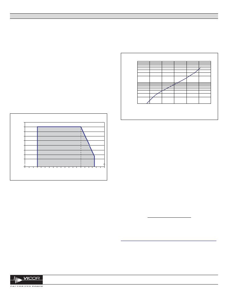
�PRM� Output� Power� Versus� VTM� Output� Power�
�As� shown� in� Figure� 17,� the� P036F048T12AL� is� rated� to� deliver� 2.5� A�
�maximum,� when� it� is� delivering� an� output� voltage� in� the� range� from�
�26� V� to� 48� V,� and� 120� W,� maximum,� when� delivering� an� output�
�voltage� in� the� range� from� 48� V� to� 55� V.� When� configuring� a� PRM� for�
�use� with� a� specific� VTM,� refer� to� the� appropriate� VTM� data� sheet.� The�
�VTM� input� power� can� be� calculated� by� dividing� the� VTM� output� power�
�by� the� VTM� efficiency� (available� from� the� VTM� data� sheet).� The� input�
�10�
�power� required� by� the� VTM� should� not� exceed� the� output� power� rating�
�of� the� PRM.�
�1�
�0�
�0.5�
�1�
�1.5�
�2�
�2.5�
�3�
�Desired� PRM� Output� Current� Limit� (A)�
�2.55�
�2.50�
�2.45�
�2.40�
�Figure� 18� —� Calculated� external� resistor� value� for� adjusting� current� limit,�
�actual� value� may� vary.�
�Input� Fuse� Recommendations�
�2.35�
�2.30�
�2.25�
�2.20�
�2.15�
�0�
�Safe� Operating� Area�
�~� ~�
�20� 22� 24� 26� 28� 30� 32� 34� 36� 38� 40� 42� 44� 46� 48� 50� 52� 54� 56� 58� 60�
�Factorized� Bu� s� Voltage� (V� f� )�
�A� fuse� should� be� incorporated� at� the� input� to� the� PRM,� in� series� with�
�the� +IN� port.� A� fast� acting� fuse,� NANO2� FUSE� 451/453� Series� 10� A�
�125� V,� or� equivalent,� may� be� required� to� meet� certain� safety� agency�
�Conditions� of� Acceptability.� Always� ascertain� and� observe� the� safety,�
�regulatory,� or� other� agency� specifications� that� apply� to� your� specific�
�application.�
�Product� Safety� Considerations�
�If� the� input� of� the� PRM� is� connected� to� SELV� or� ELV� circuits,� the� output�
�Figure� 17� —� P036F048T12AL� rating� based� on� Factorized� Bus� voltage�
�The� Factorized� Bus� voltage� should� not� exceed� an� absolute� limit� of�
�55� V,� including� steady� state,� ripple� and� transient� conditions.� Exceeding�
�this� limit� may� cause� the� internal� OVP� set� point� to� be� exceeded.�
�Parallel� Considerations�
�The� PR� port� is� used� to� connect� two� PRMs� in� parallel� to� form� a� higher�
�power� array.� When� configuring� arrays,� PR� port� interconnection�
�terminating� impedance� is� 10� k� to� SG.� See� note� Page� 8� and� refer� to�
�Application� Note� AN002.� Additionally� one� PRM� should� be� designated�
�as� the� master� while� all� other� PRMs� are� set� as� slaves� by� shorting� their�
�SC� pin� to� SG.� The� PC� pins� must� be� directly� connected� (no� diodes)� to�
�assure� a� uniform� start� up� sequence.� Consult� Vicor� applications�
�engineering� for� applications� requiring� more� than� two� PRMs.�
�of� the� PRM� can� be� considered� SELV� or� ELV� respectively.�
�If� the� input� of� the� PRM� is� connected� to� a� centralized� DC� power� system�
�where� the� working� or� float� voltage� is� above� SELV,� but� less� than� or�
�equal� to� 75� V,� the� input� and� output� voltage� of� the� PRM� should� be�
�classified� as� a� TNV-2� circuit� and� spaced� 1.3� mm� from� SELV� circuitry� or�
�accessible� conductive� parts� according� to� the� requirements� of�
�UL60950-1,� CSA� 22.2� 60950-1,� EN60950-1,� and� IEC60950-1.�
�Application� Notes�
�For� PRM� and� V?I� Chip� application� notes� on� soldering,� board� layout,�
�and� system� design� please� click� on� the� link� below:�
�http://www.vicorpower.com/technical_library/application_information/chips /�
�Applications� Assistance�
�Please� contact� Vicor� Applications� Engineering� for� assistance,�
�1-800-927-9474,� or� email� at� apps@vicorpower.com.�
�vicorpower.com�
�800-735-6200�
�V?I� Chip� Regulator�
�P036F048T12AL�
�Rev.� 1.9�
�Page� 10� of� 14�
�发布紧急采购,3分钟左右您将得到回复。
相关PDF资料
ECM06DSEH-S243
CONN EDGECARD 12POS .156 EYELET
P024F048T12AL-CB
V.I CHIP PRM REGULATOR EVAL BOAR
RB-0515S/P
CONV DC/DC 1W 5VIN 15VOUT
BCD48BH120T120A00
HALF-CHIP BUS CONVERTER EVAL BOA
RB-0512S/P
CONV DC/DC 1W 5VIN 12VOUT
A9BBG-1003F
FLEX CABLE - AFF10G/AF10/AFF10G
EBM08DTBN-S189
CONN EDGECARD 16POS R/A .156 SLD
A9BBA-0605E
FLEX CABLE - AFJ06A/AE06/AFJ06A
相关代理商/技术参数
P036RH06FJO
制造商:n/a 功能描述:Inverter Semiconductor
P036RH06FLO
制造商:n/a 功能描述:Inverter Semiconductor
P036RH06FNO
制造商:n/a 功能描述:Inverter Semiconductor 制造商:W 功能描述:135mm braded lead wire Stud (N12B8B)
P036RH12FGO
制造商:n/a 功能描述:Power Semiconductor
P036RH12FJO
制造商:n/a 功能描述:Inverter Semiconductor
P036T048T12AL
功能描述:V.I CHIP PRM REGULATOR 48V 120W RoHS:是 类别:电源 - 板载 >> DC DC 转换器(分解式) 系列:V-I Chip™, PRM™ 应用说明:Factorized Power Architecture and V-I Chips 产品培训模块:VI Chip Bus Converter Modules 标准包装:1 系列:V-I Chip™, BCM™ 类型:总线转换器模块 输出数:1 电压 - 输入(最小):330V 电压 - 输入(最大):365V 输出电压:12.5V 电流 - 输出(最大):24A 电源(瓦) - 制造商系列:300W 电压 - 隔离:4.242kV(4242V) 应用:商用 特点:具有远程开/关功能和 UVLO 安装类型:通孔 封装/外壳:模块 尺寸/尺寸:1.28" L x 0.87" W x 0.26" H(32.5mm x 22.0mm x 6.7mm) 包装:托盘 工作温度:-55°C ~ 125°C 效率:95.3% 电源(瓦特)- 最大:300W 重量:0.031 磅(14.06g)
P037253-001
制造商:Superior Electric 功能描述:Auxiliary Equipment - T5587* Paralleling Choke Cpver
P037S
制造商:Pro-Signal 功能描述:TRANSFORMER AUDIO 100V LINE 4W 制造商:PRO SIGNAL 功能描述:TRANSFORMER, AUDIO, 100V LINE, 4W